Archive

Posts Tagged ‘verilog’

Book: 100 Power Tips for FPGA Designers

May 23rd, 2011 76 comments


Front cover

This book is a collection of articles on various aspects of FPGA design: synthesis, simulation, porting ASIC designs, floorplanning and timing closure, design methodologies, performance, area and power optimizations, RTL coding, IP core selection, and many others.

The book is intended for system architects, design engineers, and students who want to improve their FPGA design skills. Both novice and seasoned logic and hardware engineers can find bits of useful information.

This book is written by a practicing FPGA logic designer, and contains a lot of illustrations, code examples, and scripts. Rather than providing information applicable to all FPGA vendors, this book edition focuses on Xilinx Virtex-6 and Spartan-6 FPGA families. Code examples are written in Verilog HDL.


Download excerpt from the book
Download source code, projects, and scripts


Paperback edition on Amazon.com , Amazon.de, and Amazon.co.uk

Number of pages: 474
Publisher: CreateSpace
ISBN:978-1461186298


Kindle edition on Amazon.com

The book can be read in color on a PC or MAC using free Kindle for PC or Kindle for MAC application.
It can also be read on an iPhone or iPad using free Kindle for iPhone or Kindle for iPad application.


Flipkart.com
Readers based in India can purchase the book on Flipkart.com


www.phei.com.cn
Chinese-speaking readers can purchase the book on PHEI


Google eBook edition
The book can be read in color on a PC, MAC, Tablet/iPad. Extensive preview is available.


ePub edition on Barnes and Noble
The book can also be read using free Nook for PC, Adobe Digital Edition applications, or on other eReaders that support ePub format.


Any questions, comments, suggestions about the book are welcome.


LFSR Counters – Part 3

May 11th, 2009 4 comments


  Here is how the LFSR Counter Generator works:

(1) Specify counter value, e.g. 200. It’s 8 bits, so the tool selects 8-bit LFSR with polynomial coefficients taken from the table in [1].

(2) Reset LFSR to 0, run a loop that shifts the LFSR 200 times. Then latch its value (LFSR_COUNT_VAL).

(3) Use that 8-bit LFSR and LFSR_COUNT_VAL to generate a Verilog code. When the LFSR hits LFSR_COUNT_VAL, it counted 200.

This approach is working because the polynomial selected in (1) has a maximum-length property. That is it generates a sequence of unique values from 0 to 2n-1.

I synthesized a 32-bit LFSR counter for Xilinx Virtex5 chip  and compared its size with a regular 32-bit counter.

Here are the results:

Module Slices Regs LUTs
regular_counter 17 32 44
lfsr_counter 10 32 7


References

  1. Peter Alfke, Efficient Shift Registers, LFSR Counters, and Long Pseudo-Random Sequence Generators, Xilinx application note Xapp052


LFSR Counters – Part 2

May 11th, 2009 No comments


  Because generating the code for LFSR counter is a computation- and memory-intensive operation, and it’s running on a server, the server usually times out after the counter value exceeds ~22 bits. I rearchitected the tool in such a way that if requested counter size is greater than 20 bit, it’s sent to a server in chunks ot 20 bits. To implement that I was using a standard AJAX approach: XmlHTPRequest and callback. That also allowed me to put a progress bar – I used  jsProgressBarHandler from Bram.us.

  Still, it’s a quite slow operation, so I limited the LFSR Counter size to 31 bit for practical purposes. There is no fundamental problem with that. It can be as large as 168 bit, it’d just take forever to complete.

I also created a stand-alone application that can generate large LFSR counters faster. Download it from SourceForge.


Parallel Scrambler Generator

May 5th, 2009 128 comments


  Scramblers are used in many communicaton protocols such as PCI Express, SAS/SATA, USB, Bluetooth to randomize the transmitted data. To keep this post short and focused I’ll not discuss the theory behind scramblers. For more information about scramblers see [1], or do some googling.  The topic of this post is the parallel implementation of a scrambler generator. Protocol specifications define scrambling algorithm using either hex or polynimial notation. This is not always suitable for efficient hardware or software implementation. Please read my post on parallel CRC Generator about that.

 The Parallel Scrambler Generator method that I’m going to describe has a lot in common with the Parallel CRC Generator. The difference is that CRC generator outputs CRC value, whereas Scrambler generator produces scrambled data. But the internal working of both based on the same principle.

Here is an example of a scrambler with the polynomial G(x) = x16+x5+x4+x3+1

scrambler1


Following is the description of the Parallel Scrambler Generator algorithm:

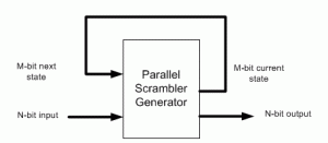
(1) Let’s denote N=data width, M=generator polynomial width. scrambler21

(2) Implement serial scrambler generator using given polynomial or hex notation. It’s easy to do in any programming language or script: C, Java, Perl, Verilog, etc. 

(3) Parallel Scrambler implementation is a function of N-bit data input as well as M-bit current state of the polynomial, as shown in the above figure. We’re going to build three matrices:

  • Mout (next state polynomial) as a function of Min(current state polynomial) when N=0 and
  • Nout as a function of Nin when Min=0. 
  • Nout as a function of Min when Nin=0

      Note that the polynomial next state doesn’t depend on the scrambled data, therefore we need only three matrices.


(4) Using the routine from (3) calculate scrambled data for the Mout values given Min, when Nin=0. Each Min value is one-hot encoded, that is there is only one bit set. 

(5) Build MxM matrix, Each row contains the results from (4) in increasing order. For example, 1’st row contains the result of input=0×1, 2′nd row is input=0×2, etc. The output is M-bit wide, which the polynomial width.

(6) Calculate the Nout values given Nin, when Min=0. Each Nin value is one-hot encoded, that is there is only one bit set. 

(7) Build NxN matrix, Each row contains the results from (6) in increasing order. The output is N-bit wide, which the data width.

(8) Calculate the Nout values given Min, when Nin=0. Each Min value is one-hot encoded, that is there is only one bit set. 

(9) Build MxN matrix, Each row contains the results from (7) in increasing order. The output is N-bit wide, which the data width.

(10) Now, build an equation for each Nout[i] bit: all Nin[j] and Min[k] set bits in column [i] from three matrices participate in the equation. The participating inputs are XORed together.


Nout is the parallel scrambled data.


Keep me posted if the Parallel Scrambler Generation tool works for you, or you need more clarifications on the algorithm.


References:

  1. Scramblers on Wiki


Parallel CRC Generator

May 5th, 2009 218 comments


Download a full version of this article


Every modern communication protocol uses one or more error detection algorithms. Cyclic Redundancy Check, or CRC, is by far the most popular one. CRC properties are defined by the generator polynomial length and coefficients. The protocol specification usually defines CRC in hex or polynomial notation. For example, CRC5 used in USB 2.0 protocol is represented as 0x5 in hex notation or as G(x)=x5+x2+1 in the polynomial. This CRC is implemented in hardware as a shift register as shown in the following picture.crc5

The problem is that in many cases shift register implementation is suboptimal. It only allows the calculation of one bit every clock. If a design has 32-bit wide datapath, meaning that every clock CRC module has to calculate CRC on 32-bit of data, this scheme will not work. Somehow this serial shift register implementation has to be converted into a parallel N-bit wide circuit, where N is the design datapath width, so that every clock N bits are processed.

I started researching the available literature on parallel CRC calculation methods and found only a handful of papers ([2], [3]) that deal with this issue. Most sources are academic and focus on the theoretical aspect of the problem. They are too impractical to implement in software or hardware for a quick code generation.

I came up with the following scheme that I’ve used to build an online Parallel CRC Generator tool. Here is a description of the steps in which I make use USB CRC5 mentioned above.    crc5-parallel
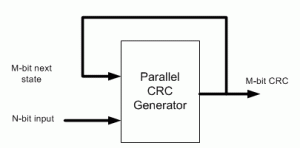
(1) Let’s denote N=data width, M=CRC width. For example, if we want to generate parallel USB CRC5 for 4-bit datapath, N=4, M=5.

(2) Implement serial CRC generator routine using given polynomial or hex notation. It’s easy to do in any programming language or script: C, Java, Perl, Verilog, etc.

(3) Parallel CRC implementation is a function of N-bit data input as well as M-bit current state CRC, as shown in the above figure. We’re going to build two matrices: Mout (next state CRC) as a function of Min(current state CRC) when N=0 and Mout as a function of Nin when M=0.

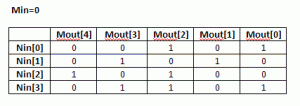
(4) Using the routine from (2) calculate CRC for the N values when Min=0. Each value is one-hot encoded, that is there is only one bit set. For N=4 the values are 0x1, 0x2, 0x4, 0x8.  Mout = F(Nin,Min=0)

(5) Build NxM matrix, Each row contains the results from (3) in increasing order. For example, 1’st row contains the result of input=0x1, 2’nd row is input=0x2, etc. The output is M-bit wide, which the desired CRC width. Here is the matrix for USB CRC5 with N=4.
matrix1

(6) Each column in this matrix, and that’s the interesting part, represents an output bit Mout[i] as a function of Nin.

(7) Using the routine from (3) calculate CRC for the M values when Nin=0. Each value is one-hot encoded, that is there is only one bit set. For M=5 the values are 0x1, 0x2, 0x4, 0x8, 0x10.  Mout = F(Nin=0,Min)

(8) Build MxM matrix, Each row contains the results from (7) in increasing order. Here is the matrix for USB CRC5 with N=4
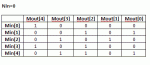
matrix2(9) Now, build an equation for each Mout[i] bit: all Nin[j] and Min[k] bits in column [i] participate in the equation. The participating inputs are XORed together.

Mout[0] = Min[1]^Min[4]^Nin[0]^Nin[3]

Mout[1] = Min[2]^Nin[1]

Mout[2] = Min[1]^Min[3]^Min[4]^Nin[0]^Nin[2]^Nin[3]

Mout[3] = Min[2]^Min[4]^Nin[1]^Nin[3]

Mout[4] = Min[0]^Min[3]^Nin[2]

That is our parallel CRC.

I presume since the invention of the CRC algorithm more than 40 years ago, somebody has already came up with this approach. I just coulnd’t find it and “reinvented the wheel”.

Keep me posted if the CRC Generation tool works for you, or you need more clarifications on the algorithm.


[September 29th, 2010] Users frequently ask why their implementation of serial CRC doesn’t match the generated parallel CRC with the same polynomial. There are few reasons for that:
– bit order into serial CRC isn’t the same as how the data is fed into the parallel CRC
– input data bits are inverted
– LFSR is not initialized the same way. A lot of protocols initialize it with F-s, and that’s what is done in the parallel CRC.


Download a full version of this article


Error Control Coding


References

  1. CRC on Wikipedia
  2. G. Campobello, G Patane, M Russo, “Parallel CRC Realization”
  3. W Lu, S. Wong, “A Fast CRC Update Implementation”


LFSR Counters

May 4th, 2009 37 comments


  Most of the EE or CS graduates know or at least have heard about different types of hardware counters: prescaled, Johnson, ripple carry, linear feedback shift register (LFSR), and others.
The majority of logic designers use the first two types, because they’re simple to implement in Verilog or VHDL. However, for some applications LFSR counters offer a significant advantage in terms of logic utilization and maximum frequency.
The other day I run into Xilinx LFSR Counter core and decided to explore its advantages. I was so impressed with its area saving comparing with regular counters that I decided to write an online tool that generates a Verilog code for an LFSR counter of an arbitrary value.
This LFSR Counter Generator tool is running on the server. The time it takes to generate the code depends exponentially on the counter size. It takes several seconds to generate a 20-bit counter. But bigger counters cause the server to timeout with the current tool implementation.
I’m planning to tweak the implementation to be able to generate counters up to ~30 bits. More than that would take too long no matter what approach is taken.

The Art of Error Correcting Coding

Please post you comments about the experience with the tool, features you’d like to add, and the issues you’ve seen.


References:

  1. Peter Alfke, Efficient Shift Registers, LFSR Counters, and Long Pseudo-Random Sequence Generators,
    Xilinx application note  Xapp052
  2. Maria George and Peter Alfke, Linear Feedback Shift Registers in Virtex Devices, Xilinx application note  Xapp210
  3. Xilinx Linear Feedback Shift Register (LFSR) Logic Core


Welcome to OutputLogic.com

May 2nd, 2009 7 comments


  Juggling between my full time job as a logic designer and my personal life I found some time to bootstrap OutputLogic.com. I wanted to share some of the tools and ideas I’ve accumulated over the years and now it’s a good time to do so.

An important design choice that I’ve made was to have those tools entirely web-based. In my opinion, it’s so much more convenient and user-friendly than having lots of scattered applications, written in different languages, for different operating systems, and with inconsistent user interfaces.

It looks like a web browser is becoming the focal point of the user interaction with the computer. More and more high-quality web application are showing up and getting a widespread adoption. Just to mention a few: Gmail, Google Maps, Google Documents. Just a few years ago you’d use a standalone application for sending an email, finding a direction, or creating a spreadsheet.

But writing a decent web-based application requires a set of very specialized skills that takes time to acquire and master. It’s no more just cranking an HTML code and peppering it with some JavaScript. One needs to be familiar with half a dozen scripting languages, several application frameworks, databases. For lots of people it is a full-time job.
Nevertheless, another design choice was to develop everything myself. I knew it’d be quite a challenge, but that’s exactly what makes the process so fun.

I don’t have much experience doing web design, which means that implementing things that I want and how I want takes a lot more time than it should. Things like getting around JavaScript quirks, figuring out why GCI doesn’t work, debugging Perl scripts, reverse-engineering piles of PHP code, finding the right framework for the site and development tools to work with, and many others. That’s the disadvantage: the learning curve.

Sometimes it’s hard to implement a low-level feature with a high-level language, which is not designed for that task. On the other hand, it’s often so much easier to design a piece of user interface to be displayed in a browser with just a few lines of script rather than writing it almost from scratch in Java, C++, or whatever language is used for standalone applications.

In any case, that was a short introduction. Thanks for taking you time reading this post. Your valuable input to the OutputLogic.com is greatly appreciated.