Parallel CRC Generator
|
|
Download a full version of this article |
Every modern communication protocol uses one or more error detection algorithms. Cyclic Redundancy Check, or CRC, is by far the most popular one. CRC properties are defined by the generator polynomial length and coefficients. The protocol specification usually defines CRC in hex or polynomial notation. For example, CRC5 used in USB 2.0 protocol is represented as 0x5 in hex notation or as G(x)=x5+x2+1 in the polynomial. This CRC is implemented in hardware as a shift register as shown in the following picture.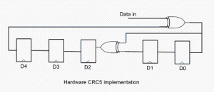
The problem is that in many cases shift register implementation is suboptimal. It only allows the calculation of one bit every clock. If a design has 32-bit wide datapath, meaning that every clock CRC module has to calculate CRC on 32-bit of data, this scheme will not work. Somehow this serial shift register implementation has to be converted into a parallel N-bit wide circuit, where N is the design datapath width, so that every clock N bits are processed.
I started researching the available literature on parallel CRC calculation methods and found only a handful of papers ([2], [3]) that deal with this issue. Most sources are academic and focus on the theoretical aspect of the problem. They are too impractical to implement in software or hardware for a quick code generation.
I came up with the following scheme that I’ve used to build an online Parallel CRC Generator tool. Here is a description of the steps in which I make use USB CRC5 mentioned above. 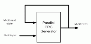
(1) Let’s denote N=data width, M=CRC width. For example, if we want to generate parallel USB CRC5 for 4-bit datapath, N=4, M=5.
(2) Implement serial CRC generator routine using given polynomial or hex notation. It’s easy to do in any programming language or script: C, Java, Perl, Verilog, etc.
(3) Parallel CRC implementation is a function of N-bit data input as well as M-bit current state CRC, as shown in the above figure. We’re going to build two matrices: Mout (next state CRC) as a function of Min(current state CRC) when N=0 and Mout as a function of Nin when M=0.
(4) Using the routine from (2) calculate CRC for the N values when Min=0. Each value is one-hot encoded, that is there is only one bit set. For N=4 the values are 0x1, 0x2, 0x4, 0x8. Mout = F(Nin,Min=0)
(5) Build NxM matrix, Each row contains the results from (3) in increasing order. For example, 1’st row contains the result of input=0x1, 2’nd row is input=0x2, etc. The output is M-bit wide, which the desired CRC width. Here is the matrix for USB CRC5 with N=4.
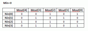
(6) Each column in this matrix, and that’s the interesting part, represents an output bit Mout[i] as a function of Nin.
(7) Using the routine from (3) calculate CRC for the M values when Nin=0. Each value is one-hot encoded, that is there is only one bit set. For M=5 the values are 0x1, 0x2, 0x4, 0x8, 0x10. Mout = F(Nin=0,Min)
(8) Build MxM matrix, Each row contains the results from (7) in increasing order. Here is the matrix for USB CRC5 with N=4
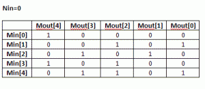 (9) Now, build an equation for each Mout[i] bit: all Nin[j] and Min[k] bits in column [i] participate in the equation. The participating inputs are XORed together.
Mout[0] = Min[1]^Min[4]^Nin[0]^Nin[3]
Mout[1] = Min[2]^Nin[1]
Mout[2] = Min[1]^Min[3]^Min[4]^Nin[0]^Nin[2]^Nin[3]
Mout[3] = Min[2]^Min[4]^Nin[1]^Nin[3]
Mout[4] = Min[0]^Min[3]^Nin[2]
That is our parallel CRC.
I presume since the invention of the CRC algorithm more than 40 years ago, somebody has already came up with this approach. I just coulnd’t find it and “reinvented the wheel”.
Keep me posted if the CRC Generation tool works for you, or you need more clarifications on the algorithm.
[September 29th, 2010] Users frequently ask why their implementation of serial CRC doesn’t match the generated parallel CRC with the same polynomial. There are few reasons for that:
– bit order into serial CRC isn’t the same as how the data is fed into the parallel CRC
– input data bits are inverted
– LFSR is not initialized the same way. A lot of protocols initialize it with F-s, and that’s what is done in the parallel CRC.
|
|
Download a full version of this article |
References
- CRC on Wikipedia
- G. Campobello, G Patane, M Russo, “Parallel CRC Realization”
- W Lu, S. Wong, “A Fast CRC Update Implementation”

Hi Rucha,
Yes, there are efficient ways to handle different data widths. Those are beyond the scope of this CRC generator tool, and I’ve been using them in different FPGA/ASIC designs.
Thanks,
Evgeni
Hi,
I want to implement CRC 32 with 4K data. But my bus width is 256 bits. So I need to feed multiple slabs of 256 bits and use the previous crc as new seed in present clock cycle. Any idea how that can be implemented?
Hi,
Yes, implement exactly as you described. Very first 256-bit chunk is seeded with all-FFs (or whatever your CRC32 specification requires). Consequent 256-bit chunks are seeded with the result of the previous calculation.
Thanks,
Evgeni
@Evgeni
Understood. No manipulations need to be made to the code. But how does one feed the data to the generator then? Because I know giving it one data input will just make it work with that data and its old CRC. If I have to give a second data, how do i do that?
Hi,
You said there is 4K data, or 16 chunks of 256bit. So there is a mux on the input of CRC data, and each clock you select the right part of the data.
Thanks,
Evgeni
@Evgeni
Thank you so much. That makes sense.
Hi,
Is it possible to use the same the parallel generator for two different data widths? I am trying to use crc32 for 64 bits and then my last data word is only 32 bits so I wanted to seed a 32 bit crc32 with the final output of the 64 bit one and then perform the calculation with the last of the data. I’m not sure if this is possible so I tried a simple test of processing 1 64 bit word with the 64 bit generator and the same 64 bit word in two cycles on the 32 bit generator. I would think that these would give the same result but they appear to be very different output values. Should these values be different or am I doing something wrong?
Hi Austin,
Yes, you can process 64bit word in two cycles, 32bit each. It’s the same thing as, for example, processing 64bit words in 64 cycles using serial CRC, or any other multiple. Most likely reason why it doesn’t work is bit/byte ordering.
I’ve developed a technique that enables processing remaining 32bit with the same 64bit CRC. This is actually a simple case. I’ve recently used it in a design with 2048bit data bus and data that ends at any byte boundary; all that was processed with a single 2048 data bit CRC module. That technique is not publicly available, though.
Thanks,
Evgeni
Hi madam
can you please help me for checking parallel crc for the polynomial x11+x9+x8+x7+x5+x4+x2+x+1 with data width = 12bit. i am new to fpga designs.
Thanks, very useful!
in parallel crc implementation .i am using crc 16 for 256 bit data ,will it completes in on e clock cycle?
hi
what is the notation the output logic parallel crc generator uses for data and crc poly , means normal or reversed or koopman reversed reciprocal ?
on every clock cycle the input data was 256bit. whole for a 16 clocks 16×256=4k data.is it possible to implement using crc 16 parallel crc within 16 clocks?
The suggestion that 0x5 represents x^5 + x^2 + 1 cannot be correct!
0x5 would either be x^3 + x^1 + 1 using implicit-1 notation or x^2 + 1 otherwise.
Please see:
https://users.ece.cmu.edu/~koopman/crc/crc5.html
If using implicit-1 notation, the correct hex representation is 0x12.
I believe this video will be of help – visualisation of CRC and Parallel CRC on FPGA:
https://www.youtube.com/watch?v=FzeuaVNnke8
@Michael Etzkorn
This is a third form of notation “implicit MSB”… :^)
Hi Evgeni, hope you still check these comments.
Thanks for the article, it’s been very useful in our work here at my company.
I can follow through your process right up until the last step, XORing the two matrices together. How do you know this is what we have to do? Maybe there is something obvious I’m missing, or maybe there is a fundamental inherent property of the CRC function that enables this that I am unaware of.
Thanks, Sam
if the data size is variable (i.e., from 1 byte to 128 bytes, it can be anything) then is there any optimized way for calculating lfsr_s without having 128 cases?
Hi Praveen,
There are multiple ways to deal with CRC on misaligned data. One way is to pad zeros to 128 bytes before the first byte, adjust LFSR init value, and use the same CRC for 128 bytes (can be used in packet starts, for example). Another way is to extend zeros after the last byte to 128 bytes, and adjust calculated CRC (for packet ends). Sometimes, misaligned data needs to be both padded before the first byte and after the last byte to align with 128 byte. Then both LFSR init and CRC need to be adjusted.
I’ve developed IP cores that do the above adjustments, but they’re not open source and not publicly available.
Thanks,
Evgeni