Archive

Posts Tagged ‘parallel crc’

Parallel Scrambler Generator

May 5th, 2009 128 comments


  Scramblers are used in many communicaton protocols such as PCI Express, SAS/SATA, USB, Bluetooth to randomize the transmitted data. To keep this post short and focused I’ll not discuss the theory behind scramblers. For more information about scramblers see [1], or do some googling.  The topic of this post is the parallel implementation of a scrambler generator. Protocol specifications define scrambling algorithm using either hex or polynimial notation. This is not always suitable for efficient hardware or software implementation. Please read my post on parallel CRC Generator about that.

 The Parallel Scrambler Generator method that I’m going to describe has a lot in common with the Parallel CRC Generator. The difference is that CRC generator outputs CRC value, whereas Scrambler generator produces scrambled data. But the internal working of both based on the same principle.

Here is an example of a scrambler with the polynomial G(x) = x16+x5+x4+x3+1

scrambler1


Following is the description of the Parallel Scrambler Generator algorithm:

(1) Let’s denote N=data width, M=generator polynomial width. scrambler21
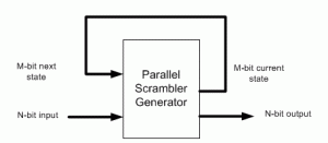
(2) Implement serial scrambler generator using given polynomial or hex notation. It’s easy to do in any programming language or script: C, Java, Perl, Verilog, etc. 

(3) Parallel Scrambler implementation is a function of N-bit data input as well as M-bit current state of the polynomial, as shown in the above figure. We’re going to build three matrices:

  • Mout (next state polynomial) as a function of Min(current state polynomial) when N=0 and
  • Nout as a function of Nin when Min=0. 
  • Nout as a function of Min when Nin=0

      Note that the polynomial next state doesn’t depend on the scrambled data, therefore we need only three matrices.


(4) Using the routine from (3) calculate scrambled data for the Mout values given Min, when Nin=0. Each Min value is one-hot encoded, that is there is only one bit set. 

(5) Build MxM matrix, Each row contains the results from (4) in increasing order. For example, 1’st row contains the result of input=0×1, 2′nd row is input=0×2, etc. The output is M-bit wide, which the polynomial width.

(6) Calculate the Nout values given Nin, when Min=0. Each Nin value is one-hot encoded, that is there is only one bit set. 

(7) Build NxN matrix, Each row contains the results from (6) in increasing order. The output is N-bit wide, which the data width.

(8) Calculate the Nout values given Min, when Nin=0. Each Min value is one-hot encoded, that is there is only one bit set. 

(9) Build MxN matrix, Each row contains the results from (7) in increasing order. The output is N-bit wide, which the data width.

(10) Now, build an equation for each Nout[i] bit: all Nin[j] and Min[k] set bits in column [i] from three matrices participate in the equation. The participating inputs are XORed together.


Nout is the parallel scrambled data.


Keep me posted if the Parallel Scrambler Generation tool works for you, or you need more clarifications on the algorithm.


References:
  1. Scramblers on Wiki


Parallel CRC Generator

May 5th, 2009 218 comments


Download a full version of this article


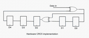
Every modern communication protocol uses one or more error detection algorithms. Cyclic Redundancy Check, or CRC, is by far the most popular one. CRC properties are defined by the generator polynomial length and coefficients. The protocol specification usually defines CRC in hex or polynomial notation. For example, CRC5 used in USB 2.0 protocol is represented as 0x5 in hex notation or as G(x)=x5+x2+1 in the polynomial. This CRC is implemented in hardware as a shift register as shown in the following picture.crc5

The problem is that in many cases shift register implementation is suboptimal. It only allows the calculation of one bit every clock. If a design has 32-bit wide datapath, meaning that every clock CRC module has to calculate CRC on 32-bit of data, this scheme will not work. Somehow this serial shift register implementation has to be converted into a parallel N-bit wide circuit, where N is the design datapath width, so that every clock N bits are processed.

I started researching the available literature on parallel CRC calculation methods and found only a handful of papers ([2], [3]) that deal with this issue. Most sources are academic and focus on the theoretical aspect of the problem. They are too impractical to implement in software or hardware for a quick code generation.

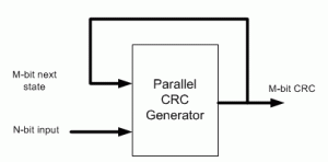
I came up with the following scheme that I’ve used to build an online Parallel CRC Generator tool. Here is a description of the steps in which I make use USB CRC5 mentioned above.    crc5-parallel

(1) Let’s denote N=data width, M=CRC width. For example, if we want to generate parallel USB CRC5 for 4-bit datapath, N=4, M=5.

(2) Implement serial CRC generator routine using given polynomial or hex notation. It’s easy to do in any programming language or script: C, Java, Perl, Verilog, etc.

(3) Parallel CRC implementation is a function of N-bit data input as well as M-bit current state CRC, as shown in the above figure. We’re going to build two matrices: Mout (next state CRC) as a function of Min(current state CRC) when N=0 and Mout as a function of Nin when M=0.

(4) Using the routine from (2) calculate CRC for the N values when Min=0. Each value is one-hot encoded, that is there is only one bit set. For N=4 the values are 0x1, 0x2, 0x4, 0x8.  Mout = F(Nin,Min=0)

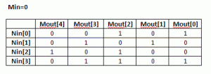
(5) Build NxM matrix, Each row contains the results from (3) in increasing order. For example, 1’st row contains the result of input=0x1, 2’nd row is input=0x2, etc. The output is M-bit wide, which the desired CRC width. Here is the matrix for USB CRC5 with N=4.

matrix1

(6) Each column in this matrix, and that’s the interesting part, represents an output bit Mout[i] as a function of Nin.

(7) Using the routine from (3) calculate CRC for the M values when Nin=0. Each value is one-hot encoded, that is there is only one bit set. For M=5 the values are 0x1, 0x2, 0x4, 0x8, 0x10.  Mout = F(Nin=0,Min)

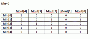
(8) Build MxM matrix, Each row contains the results from (7) in increasing order. Here is the matrix for USB CRC5 with N=4

matrix2(9) Now, build an equation for each Mout[i] bit: all Nin[j] and Min[k] bits in column [i] participate in the equation. The participating inputs are XORed together.

Mout[0] = Min[1]^Min[4]^Nin[0]^Nin[3]

Mout[1] = Min[2]^Nin[1]

Mout[2] = Min[1]^Min[3]^Min[4]^Nin[0]^Nin[2]^Nin[3]

Mout[3] = Min[2]^Min[4]^Nin[1]^Nin[3]

Mout[4] = Min[0]^Min[3]^Nin[2]

That is our parallel CRC.

I presume since the invention of the CRC algorithm more than 40 years ago, somebody has already came up with this approach. I just coulnd’t find it and “reinvented the wheel”.

Keep me posted if the CRC Generation tool works for you, or you need more clarifications on the algorithm.


[September 29th, 2010] Users frequently ask why their implementation of serial CRC doesn’t match the generated parallel CRC with the same polynomial. There are few reasons for that:
– bit order into serial CRC isn’t the same as how the data is fed into the parallel CRC
– input data bits are inverted
– LFSR is not initialized the same way. A lot of protocols initialize it with F-s, and that’s what is done in the parallel CRC.


Download a full version of this article


Error Control Coding


References

  1. CRC on Wikipedia
  2. G. Campobello, G Patane, M Russo, “Parallel CRC Realization”
  3. W Lu, S. Wong, “A Fast CRC Update Implementation”