Parallel CRC Generator
|
|
Download a full version of this article |
Every modern communication protocol uses one or more error detection algorithms. Cyclic Redundancy Check, or CRC, is by far the most popular one. CRC properties are defined by the generator polynomial length and coefficients. The protocol specification usually defines CRC in hex or polynomial notation. For example, CRC5 used in USB 2.0 protocol is represented as 0x5 in hex notation or as G(x)=x5+x2+1 in the polynomial. This CRC is implemented in hardware as a shift register as shown in the following picture.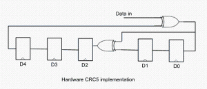
The problem is that in many cases shift register implementation is suboptimal. It only allows the calculation of one bit every clock. If a design has 32-bit wide datapath, meaning that every clock CRC module has to calculate CRC on 32-bit of data, this scheme will not work. Somehow this serial shift register implementation has to be converted into a parallel N-bit wide circuit, where N is the design datapath width, so that every clock N bits are processed.
I started researching the available literature on parallel CRC calculation methods and found only a handful of papers ([2], [3]) that deal with this issue. Most sources are academic and focus on the theoretical aspect of the problem. They are too impractical to implement in software or hardware for a quick code generation.
I came up with the following scheme that I’ve used to build an online Parallel CRC Generator tool. Here is a description of the steps in which I make use USB CRC5 mentioned above. 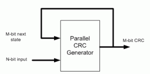
(1) Let’s denote N=data width, M=CRC width. For example, if we want to generate parallel USB CRC5 for 4-bit datapath, N=4, M=5.
(2) Implement serial CRC generator routine using given polynomial or hex notation. It’s easy to do in any programming language or script: C, Java, Perl, Verilog, etc.
(3) Parallel CRC implementation is a function of N-bit data input as well as M-bit current state CRC, as shown in the above figure. We’re going to build two matrices: Mout (next state CRC) as a function of Min(current state CRC) when N=0 and Mout as a function of Nin when M=0.
(4) Using the routine from (2) calculate CRC for the N values when Min=0. Each value is one-hot encoded, that is there is only one bit set. For N=4 the values are 0x1, 0x2, 0x4, 0x8. Mout = F(Nin,Min=0)
(5) Build NxM matrix, Each row contains the results from (3) in increasing order. For example, 1’st row contains the result of input=0x1, 2’nd row is input=0x2, etc. The output is M-bit wide, which the desired CRC width. Here is the matrix for USB CRC5 with N=4.
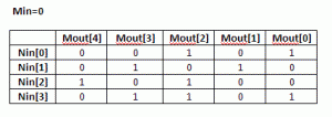
(6) Each column in this matrix, and that’s the interesting part, represents an output bit Mout[i] as a function of Nin.
(7) Using the routine from (3) calculate CRC for the M values when Nin=0. Each value is one-hot encoded, that is there is only one bit set. For M=5 the values are 0x1, 0x2, 0x4, 0x8, 0x10. Mout = F(Nin=0,Min)
(8) Build MxM matrix, Each row contains the results from (7) in increasing order. Here is the matrix for USB CRC5 with N=4
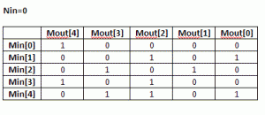 (9) Now, build an equation for each Mout[i] bit: all Nin[j] and Min[k] bits in column [i] participate in the equation. The participating inputs are XORed together.
Mout[0] = Min[1]^Min[4]^Nin[0]^Nin[3]
Mout[1] = Min[2]^Nin[1]
Mout[2] = Min[1]^Min[3]^Min[4]^Nin[0]^Nin[2]^Nin[3]
Mout[3] = Min[2]^Min[4]^Nin[1]^Nin[3]
Mout[4] = Min[0]^Min[3]^Nin[2]
That is our parallel CRC.
I presume since the invention of the CRC algorithm more than 40 years ago, somebody has already came up with this approach. I just coulnd’t find it and “reinvented the wheel”.
Keep me posted if the CRC Generation tool works for you, or you need more clarifications on the algorithm.
[September 29th, 2010] Users frequently ask why their implementation of serial CRC doesn’t match the generated parallel CRC with the same polynomial. There are few reasons for that:
– bit order into serial CRC isn’t the same as how the data is fed into the parallel CRC
– input data bits are inverted
– LFSR is not initialized the same way. A lot of protocols initialize it with F-s, and that’s what is done in the parallel CRC.
|
|
Download a full version of this article |
References
- CRC on Wikipedia
- G. Campobello, G Patane, M Russo, “Parallel CRC Realization”
- W Lu, S. Wong, “A Fast CRC Update Implementation”

Hi,
I couldn’t understand how to calculate the (Nin=0, Min) case. how i should enter data to CRC calculator in order to calculate Min=0x1,0x2, etc.
Thanks in advance
Dear Evgeni,
I generated crc module for ethernet with 32 bit polynomial and 32 bit data input.
Used a standard udp frame and made a small testbench to test crc verilog module.
Calculated crc online http://www.lammertbies.nl/comm/info/crc-calculation.html
The 2 outputs donot match. Tried byte-reflect from its least-significant-bit-first order to the normal most-significant-bit first order. Does not seem to match.
Do I need to do something else ?
Thanks in advance!
Evgeni,
I found the answer in the comments section.
Thanks for providing the tool.
full version of this document pdf file has some typo.
Mout[0] = Min[1] ^ Min[4] ^ Min[0] ^ Min[3]
-> Mout[0] = Min[1] ^ Min[4] ^ Nin[0] ^ Nin[3]
Shouldn’t the crc_out be 1 bit less (in width) than the polynom itself? I see crc_out in the width of the polynom I inserted.
while making wcb castings we are using crc materials. what about the role of crc
can you help me
Hi
I am using the crc32 generator code from this site for poly : 04C11DB7 for data width 128.
I am using it in my code and I have to do the verification for which I am writing the following function
function bit[31:0] crc32_8(bit [31:0] accum, bit [127:0] data);
bit [31:0] local_accum = accum;
bit [7:0] local_data = data;
for (int j=0; j> 1) ^ ( (((local_data[j] & 1) ^ (local_accum & 1)) == 1) ? 32’hEDB88320 : 0 );
local_data[j] = local_data[j] >> 1;
end
return local_accum;
endfunction : crc32_8
but the answers are not matching. Do I need to take a complement and reverse the crc?
Can someone please help?
Hi,
I have a question. I am using the crc32 generator code from this site for poly : 04C11DB7 for data width 32 and 16. Theoretically, the result of 32-bits data should be cascaded result of 2 16-bit data like following code,
assign crc32_d32 = gen_crc32_d32(data[31:0], crc_in);
assign crc32_d16_l = gen_crc32_d16(data[15:0], crc_in);
assign crc32_d16_h = gen_crc32_d16(data[31:16],crc32_d16_l);
I think crc32_d32 should be equal to crc32_d16_h, but the simulation result is not for data that is not 32’h0.
Can anyone tell me why these 2 results are different?
Hi,
First thing is to make it work with 1-bit data, to eliminate the possibility of incorrect bit/byte order. That’s usually the source of most of the problems.
Thanks,
Evgeni
@Evgeni
Hi, Evgeni,
I had tried to implement 1-bit and loop 32 times, but got different result with 32-bits/round and 16-bits 2 rounds. Suppose I should get 16-bits/round result after 16-th loop and 32-bits/round result at 32-th loop. I completely confused….
That’s correct,
You shoud get the same results with 32 data bit single round, 1 data bit 32 rounds, and 16 data bits 2 rounds.
Thanks,
Evgeni
I have a problem to download the VHDL implementation code when i set up my data length and polynom length. Is the generator link somehow broken?
Hi,
I cannot reproduce this problem. Can you please specify data and polynom you’re using ?
Thanks,
Evgeni
@Evgeni
I want to test a data width of 6 bits with a crc16. When i run the first setup, it says:
“Selected USB 2.0 CRC16 and data width=6. Proceed to Step 2”. It is marked as green.
When I try to download the code in step 2 as verilog or vhdl file nothing happens.
I am designing an Ethernet application where I am required to form the packet payload at a rate of 128-bits each clock. However, each clock, from 1 to 4 of the 32-bit words forming the 128 bits will be valid.
Can I use 4 32-bit CRC generators concurrently (1 for each of the 4 32-bit streams) and then combine the 4 CRC results at the end of the payload to form the complete CRC32 for the packet? Can the 4 partial results be easily combined?
Any suggestions would be much appreciated. Thanks.
Hi,
Each of the four streams will look like this: “….D000D000D000…”, where each nibble in that string is 32-bit. “D” is a data dword, followed by 3 dwords of zeros. So after each 32-bit CRC calculation on data, you’d need to multiply the result by X^96.
Thanks,
Evgeni
Thank you for your reply. However, I didn’t really understand your answer. I will clarify my question.
I have 32-bit words, arriving in a 128-bit bus, that I must generate a 32-bit CRC for. Each clock, the 128-bit bus will either have the 1st, the 1st two, the 1st three, or all four 32-bit words valid. I must add these 1 to 4 words to my 32-bit CRC in one clock. This repeats each clock until the end of data. How do I generate my 32-bit CRC given I have a varying (1 to 4) number of words to add each clock? Can I use a 128in-32out CRC generator and set the invalid words to zeros? Will this give the proper result (the zeroed words not affecting the CRC result)? OR can I use 4 32in-32out CRC generators, 1 on each lane of the 128-bit bus, and get 4 CRC sub-results and then combine them? Will this work; how to combine? OR is there another approach? Thank you so much for your advice! Great website BTW.
Hi Stephen,
I understand your question. This is, in fact, one of the most frequently asked things. The simplest approach is to have 4 CRC generators for 32-, 64-, 96-, and 128-bit data. Then select the output based on the number of valid words. There are more complex solutions involving finite field arithmetics that help save some area. But I haven’t yet seen those in public domain. If I have some time, I’ll enhance this CRC generator. But it’s not a priority.
Thanks,
Evgeni
Thank you for your suggestion. It sounds like I would use the combinational CRC result from all 4 generators and feed them through a 4-to-1 Mux to a single 32-bit registered CRC output. In this manner, the CRC registered output is properly updated, with 1 to 4 added words, each clock. Did I understand you correctly? OR are you suggesting I can use the 4 CRC generator registered outputs?
Hi Stephen,
Yes, that’s the common practice.
Here is the reference you might find useful. See chapter 12 on page 89.
https://www.altera.com/content/dam/altera-www/global/en_US/pdfs/literature/manual/stx_cookbook.pdf
Thanks,
Evgeni
Hi Evgeni,
Thank you very much for the help!
The cookbook is also very useful.
Your website is wonderful and laid out very nicely. I will read the other parts of it as I get time, it looks very interesting.
-Stephen
Hi Evgeni,
Let say for example that we have a datapath of 256 bits. Is it possible to compute the first 128 bytes CRC and the second 128 bytes CRC at the same time, and then combine them (so without injecting the first result in the second computation)?
Thanks!
Hi Richard,
This question about “interleaved” CRC calculation comes up quite often. The short answer is – not quite. One problem is that you need to account for 128-bit of leading and trailing zeros when calculating CRC on split data:
data[255:0] = {data[255:128],128’b0} ^ {128’b0,data[127:0]}.
You can calculate CRC for each 128-bit chunk, but then you need to adjust the result by x^128 multiplication over finite field before proceeding to the next 256-bit data chunk.
Thanks,
Evgeni
Hi Evgeni,
Can you please place a testbench into the write up.
I see lot of people asking why their input don’t match outputs from crc online calculators
Namely regarding the manipulation data_in.
Thanks,
Wes
I tried running your Verilog code, for a data of 8-bit using CRC-5 used in USB 2.0, on my Xilinx ISE Design Suite 14.5 but the synthesize-process fails every time. Please help me out asap.
I try to generate the Verilog code for 16 bit width data and 16 CRC with 1+x2+x15+x16, step one works fine, but it stuck at step 2. it couldn’t generate the code for me. what is wrong with the web? I am using ie11.
Hi,
I want to do CRC32 for my 128 bit data. The input data 128 bit is coming at each clock and i want to perform crc32 for that. I generated the verilog code with 802.3 polynominal[ data width=128bit, polynominal width-32 bit] and tried to verify the functionality. I have inverted the final CRC value from the Test bench and checked for the magical number in the simulation.But i didn’t get that. the same experiments worked for 32 bit data 32 bit polynominal CRC. Can you please let me know my 128 bit data with 32 bit CRC can be implemented or not??
Hi,
Yes, it can be implemented. If 32-bit data works but 128-bit doesn’t, then the problem might be with data ordering.
Thanks,
Evgeni
Thanks, But i did n’t understand about data ordering?? can you please eloborate on this??
Hi,
Most of the problems with parallel CRCs are related to data ordering. I presume that serial CRC (when you feed one bit of data at a time) and 32-bit CRC (when you feed one DWORD of data at a time) are working.
If there is a mismatch in 128-bit CRC, one possibility is that 4 DWORDs of data are not ordered correctly (for example dw 0,1,2,3 vs. dw 3,2,1,0).
Another possibility is data misalignment. If your data doesn’t end at 128-bit boundary, you cannot include trailing zeros in 128-bit CRC calculation. There are several methods how to handle CRC checking of misaligned data.
Thanks,
Evgeni
I used the parallel CRC generator script from here and it was a breeze generating the RTL. Now i am having issues with verifying the RTL. The parallel CRC output does not match the Serial version. Here are more details:
1. LFSR is all initialzed to 0s.
2. 64 bit data width, 11 bit CRC.
3. Tried simple data case 0x0000_0000_0000_0001 and the output matches in this case. which is 0x621 the polynomial itself.
I am lost as to what the problem could be. Any help is appreciated. It is kind of urgent.
Hi,
I’d say most of the times the issue is with correct bit ordering of the data into parallel CRC. Try to invert 64 bits (such that bit[0] becomes bit[63], etc.)
Thanks,
Evgeni
@Evgeni
thanks reversing the bits helped.
now i have issue with crc output since the data fed in is non multiple of the data width.
i am padding with 0s, which i assume should be a dont care for CRC, right? but the result mismatches.
Hi,
There are multiple ways of handling misaligned data ends. Padding with zeros is not one of them.
One simple way is to have separate CRC circuits handling any possible case of misalignment, for example 8,16,…56bit.
Thanks,
Evgeni
Hi, I’m implementing a CRC with 32 bit Polynomial and 10 bits input.
I couldn’t analyse the generated code and having trouble.
Please help.
There is another typo in the full pdf article. In the simple example given of polynomial addition, the resultant poynomial shoule be:
P(x) + Q(x) = x^3 + x
The x^2 term would be eliminated by the bitwise XOR.
Thanks for finding this.
I don’t understand how you get the initial Min[0] row for the MxM case (Mout[4]=1; Mout[3]=0;Mout[2]=0;Mout[1]=0;Mout[0]=0;)
Can you give a better explanation?
Thank you.
Hello, I am trying to understand the multi-bit (parallel) implementation. When you say N is one-hot encoded, I do not really understand how we feed the input date to the CRCserial function, as its a single bit in the main function. If you could explain the implementation of the two matrices, I will clearly understand this. Thank you.
@zimn
Hi I wanted to ask how you tested your code. With a single bit data input as 0, my CRC keeps changing every clock cycle. Why is that happening? And in this situation, what is my final CRC code?
Hi Rucha,
Using non-zero CRC init value (usually all-Fs) ensures that CRC can detect all-zero input. That’s actually a feature, not a bug.
Thanks,
Evgeni
Hi Evgeni,
Thank you for your quick reply. I got around testing the serial implementation. Now I want to test the parallel implementation. I am using CRC-64-ECMA on a 256 bit data. For single bit data input of ‘1’ i get a CRC which is all 1’s except for CRC[0] (once we initialize CRC to all-Fs on reset). When I feed the parallel CRC generator with all 1’s as data (256 bit) I get a weird value of CRC. Does it take a certain number of clocks to reach the final CRC?
Hi Evgeni,
Just an update: Reading through your comments, I tried to initialize the CRC to 0 on reset. After doing this, my CRC matched for both 1 bit and 256-bit data implementation of CRC-64-ECMA. That took in the very first clock (right after reset). am I doing something wrong or is this okay as well?
Hi Rucha,
CRC is a linear circuit. So If your parallel data is 256-bit, it’d take 256 clocks for serial CRC to reach the same value as 1 clock for parallel.
One more thing to check for troubleshooting parallel CRC: try swizzling your CRC-64 output bits (bit[0] goes to bit[63], bit[1] to bit[62], etc.)
Thanks,
Evgeni
@Evgeni
Hi Evgeni,
How is it that the CRC matches when the initial value is changed to 0?
Hi Evgeni,
I tried what you said. I let the CRC be initialized to all F’s.
1. I checked bit ordering for data input of 1 bit by feeding input as 1 to CRC-64. It seems fine.
2. I then fed data input as 1 to the 256-bit data. I noted down the CRC value on reset.
I checked the CRC value after 256 clock cycles for the serial CRC data.
It still did not match. I even tried to swizzle the CRC in parallel implementation. No luck. I have ran out of solutions now.
Hi,
To implement the CRC checker, what will the data width be? I read somewhere that your software automatically does the augmentation of n- bits of 0 after the message. Then if we have to use the same generator (same width), how will we do that?
Hi Rucha,
CRC generator cannot automatically do any augmentations, because protocols use different ways to augment.
Thanks,
Evgeni
@Evgeni
Thank you for your reply. So for the same Data width, I can never use the same Generator as both a generator and a checker, Am I right? Say my Data Width is 256 bits and it generates a 64 bit CRC. So I made a checker circuit which has a data width of 320 bits (256+64) and a 64 bit CRC. This generates a value of all 0’s in the first clock when I send the data+CRC.
Is there any efficient way to do this? Or will generator and checker circuit always have to be separate because of the difference in the data width?