Parallel CRC Generator
|
|
Download a full version of this article |
Every modern communication protocol uses one or more error detection algorithms. Cyclic Redundancy Check, or CRC, is by far the most popular one. CRC properties are defined by the generator polynomial length and coefficients. The protocol specification usually defines CRC in hex or polynomial notation. For example, CRC5 used in USB 2.0 protocol is represented as 0x5 in hex notation or as G(x)=x5+x2+1 in the polynomial. This CRC is implemented in hardware as a shift register as shown in the following picture.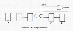
The problem is that in many cases shift register implementation is suboptimal. It only allows the calculation of one bit every clock. If a design has 32-bit wide datapath, meaning that every clock CRC module has to calculate CRC on 32-bit of data, this scheme will not work. Somehow this serial shift register implementation has to be converted into a parallel N-bit wide circuit, where N is the design datapath width, so that every clock N bits are processed.
I started researching the available literature on parallel CRC calculation methods and found only a handful of papers ([2], [3]) that deal with this issue. Most sources are academic and focus on the theoretical aspect of the problem. They are too impractical to implement in software or hardware for a quick code generation.
I came up with the following scheme that I’ve used to build an online Parallel CRC Generator tool. Here is a description of the steps in which I make use USB CRC5 mentioned above. 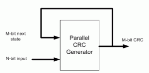
(1) Let’s denote N=data width, M=CRC width. For example, if we want to generate parallel USB CRC5 for 4-bit datapath, N=4, M=5.
(2) Implement serial CRC generator routine using given polynomial or hex notation. It’s easy to do in any programming language or script: C, Java, Perl, Verilog, etc.
(3) Parallel CRC implementation is a function of N-bit data input as well as M-bit current state CRC, as shown in the above figure. We’re going to build two matrices: Mout (next state CRC) as a function of Min(current state CRC) when N=0 and Mout as a function of Nin when M=0.
(4) Using the routine from (2) calculate CRC for the N values when Min=0. Each value is one-hot encoded, that is there is only one bit set. For N=4 the values are 0x1, 0x2, 0x4, 0x8. Mout = F(Nin,Min=0)
(5) Build NxM matrix, Each row contains the results from (3) in increasing order. For example, 1’st row contains the result of input=0x1, 2’nd row is input=0x2, etc. The output is M-bit wide, which the desired CRC width. Here is the matrix for USB CRC5 with N=4.
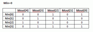
(6) Each column in this matrix, and that’s the interesting part, represents an output bit Mout[i] as a function of Nin.
(7) Using the routine from (3) calculate CRC for the M values when Nin=0. Each value is one-hot encoded, that is there is only one bit set. For M=5 the values are 0x1, 0x2, 0x4, 0x8, 0x10. Mout = F(Nin=0,Min)
(8) Build MxM matrix, Each row contains the results from (7) in increasing order. Here is the matrix for USB CRC5 with N=4
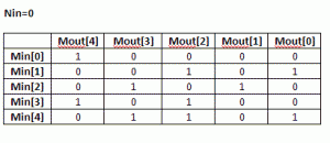 (9) Now, build an equation for each Mout[i] bit: all Nin[j] and Min[k] bits in column [i] participate in the equation. The participating inputs are XORed together.
Mout[0] = Min[1]^Min[4]^Nin[0]^Nin[3]
Mout[1] = Min[2]^Nin[1]
Mout[2] = Min[1]^Min[3]^Min[4]^Nin[0]^Nin[2]^Nin[3]
Mout[3] = Min[2]^Min[4]^Nin[1]^Nin[3]
Mout[4] = Min[0]^Min[3]^Nin[2]
That is our parallel CRC.
I presume since the invention of the CRC algorithm more than 40 years ago, somebody has already came up with this approach. I just coulnd’t find it and “reinvented the wheel”.
Keep me posted if the CRC Generation tool works for you, or you need more clarifications on the algorithm.
[September 29th, 2010] Users frequently ask why their implementation of serial CRC doesn’t match the generated parallel CRC with the same polynomial. There are few reasons for that:
– bit order into serial CRC isn’t the same as how the data is fed into the parallel CRC
– input data bits are inverted
– LFSR is not initialized the same way. A lot of protocols initialize it with F-s, and that’s what is done in the parallel CRC.
|
|
Download a full version of this article |
References
- CRC on Wikipedia
- G. Campobello, G Patane, M Russo, “Parallel CRC Realization”
- W Lu, S. Wong, “A Fast CRC Update Implementation”

hi
i am trying to implement a programmable crc read from an article could you please help me out in letting me know how a parallel crc is implented as an programmable crc.
Hi,
Can you please tell what you mean by “programmable CRC” ?
Which part do you want to program: polynomial, etc.
Thanks,
Evgeni
Hi,
I am trying to find crc-16 with following polynomial (scsi t10 crc).
polynomial=(0 1 2 4 5 7 8 9 11 15 16).
I couldnt find it anywhere. It would be great if you can add a support on your site to download this.
Hi,
I don’t have that specification. Can you please point me to it if it’s available online. I’ll take a look and add the support for its CRC16.
Thanks,
Evgeni
My impression is that the generated CRC code is the plain straight-forward matrix
resulting from directly mapping input x^i to (x^i) mod p.
While this might have been appropriate for input width of up to 128,
for high speed and higher input width (the tool allows 1024)
this results in a very poor circuit.
There are much better methods, some of then known for a longer time.
For example
Ren´e J. Glaise. A two-step computation of cyclic
redundancy code CRC-32 for ATM networks. IBM
Journal of Research and Development, 41(6):705–
710, 1997.
Andreas
Hi Andreas,
You’re right, the generated code is a plain XOR tree. I’ve used it in several commercial products, ranging from 8 to 256-bit data width and running at high speed. I agree that it’s not the most optimized implementation both in terms of area and performance. The biggest advantage of this method is that it’s practical and very configurable. I’ve also experimented with other methods that are briefly discussed in this article.
Thanks,
Evgeni
Hi,
I’ve used your crc-gen to creat vhdl code for 20 bit input data, with a 6th power CRC Generator poly 2^6 + 2^1 + 2^0 and I am expecting a 6 bit checksum output.
However, I don’t know how many clock pulses are needed to generate the required output, can you advise me please.
Also in you pdf file the example shows the CRC poly on the command line as a number 5 but this gave an error, I found that I had to enter it as 0x05 – is this
right?
my full command line in this case was
crc-gen.exe vhdl 20 5 0x05 > crcgen.txt
Thanks
Robert Phillips
Hi Robert,
It takes one clock to calculate CRC for any polynomial and data sizes.
Yes, the polynomial parameter is in hex notation.
Thanks,
Evgeni
Is there a convenient way to make the width dynamic for the last computation to serve say XGMII 10G Ethernet? Otherwise, I need 8 CRC checkers, and mux select the result at the end.
Thanx….Andrew
Hi Andrew,
There is an algorithm known as “byte-enable parallel CRC” described in this paper. However, the current approach of this site used for parallel CRC generation doesn’t support it.
Thanks,
Evgeni
Hi,
I am trying to use your CRC to send 100MBit Ethernet II frames from an FPGA. However, I still cannot receive frames, only the crc error counter increases (on the pc side). Do you know something about the specific way to append the crc32 to the Ethernet frame? I have heard several different statements about bit- and byte order and inversion of the result etc. and I tried about 12 different methods and none worked.
Thanks
Hi,
Have you tried selecting the “CRC32 for 802.3” from the drop-down protocol box ? This is the one used for Ethernet CRC32 calculation.
Another thing to try in order to rule out data ordering issues is serial CRC: the same polynomial, but data width 1.
Thanks,
Evgeni
Hi,
I am using the CRC32 for 802.3. I also tried to reverse the bit order of the input (using a respective VHDL construct) without success.
Thanks
Hi Jonas,
Depending on the implementation, it might also require swizzling CRC bits. Can you please try one of the Ethernet CRC implementations available on OpenCores.org, for example this one.
Thanks,
Evgeni
Hello again Evgeni,
Great stuff, thanks!
You probably already know this but in your Circuit Cellular article page 43 you have typo:
Mout[0] = Min[1] ^ Min[4] ^ Min[0] ^ Min[3]
should be :
Mout[0] = Min[1] ^ Min[4] ^ Nin[0] ^ Nin[3]
Also if you want to include a makefile for linux users for crc-gen here it is:
crc-gen: crc-gen.cpp
g++ -o crc-gen crc-gen.cpp
I had to comment out “#include ” in stdafx.h to make it compile too.
-m
Hi Max,
Yes, there is a typo. Another one is on page 42. It should be : P(x) + Q(x) = x^3 + x. I communicated those to the editor, and it should be somewhere on the CC errata site.
Yes, I’ll include a small makefile to get the code compiled for Linux users.
Thanks,
Evgeni
Hi Evgeni,
I am having some trouble implementing a CRC module generated from your web site. Please can you offer some ideas as to what is going wrong?
I generated the CRC code for 24bit data and with the polymonial: 1+x^1+x^5+x^6+x^23+x^24
In a simulator on consecutive clocks, after a reset, I input the data
0x72E729, 0xFCAFCD, and 0x0
This gives a CRC output of 0x324AA5
Then after another reset I input the data
0x72E729, 0xFCAFCD, and 0x324AA5
As I understand it, this should give a CRC output of 0, but instead I get 0xC475B7.
Using a speadsheet, have implemented a serial CRC for this polynomial, and using the same data I do get a value of 0.
Any ideas or suggestions will be greatfully received.
Best Regards,
Steve
Hi Steve,
Can you generate CRC code with the same polynomial but data width of 1, which is a serial CRC. Then compare its results with your spreadsheet.
Thanks,
Evgeni
@Evgeni
Hi Evgeni,
Thank you for your quick reply. Apologies for my late one!
I am trying to implement this comment from the wikipedia page you link to:
Sometimes an implementation appends n 0-bits (n being the size of the CRC) to the bitstream to be checked before the polynomial division occurs. This has the convenience that the remainder of the original bitstream with the check value appended is exactly zero, so the CRC can be checked simply by performing the polynomial division on the received bitstream and comparing the remainder with zero.
It appears that my test implementation of a serial CRC generator is different to yours in that I inject my serial data into the end of the LFSR. As described in my original message, it gives a zero result for the data stream 0×72E729, 0xFCAFCD, 0×324AA5.
For your generated code, if I use the data stream: 0×72E729, 0xFCAFCD, 0×0, 0×324AA5, I get a zero result. This works for CRC generators of both 1 and 24 bit data width.
I have not had any time to find out why this, but the result is good enough for now.
Best regards,
Steve
Hi Evgeni,
Thank you for documenting your thoughts and procedure. Your article provided a key insight in my implementation of a software CRC generator which must operate within very tight time constraints.
Thanks again!
David
Your CRC tool rocks. I use it in a lot of my projects both at home and at work. Thanks!
Hi Evgeni
I have implemented two different CRC circuits in VHDL. They are based on the common polynomial x8 + x2 +x1 + 1 and I am using the circuits to operate on 1 byte per cycle. Right now I am in conflict with another engineer about them. The psuedo code for the serial portion of the crc is below. Can you comment on the two implementations and which one is correct?
The first circuit is as follows:
P(x) = x8+ x2+ x1+ x0
assign inv = datain ^ CRC[7]; //
always @(posedge BITSTRB or posedge CLEAR) begin
if (CLEAR) begin
CRC = FF; // Init before calculation
end
else begin
CRC[7] = CRC[6];
CRC[6] = CRC[5];
CRC[5] = CRC[4];
CRC[4] = CRC[3];
CRC[3] = CRC[2];
CRC[2] = CRC[1] ^ inv;
CRC[1] = CRC[0] ^ inv;
CRC[0] = inv;
end
end
Note that we initialize our checksum to FF upon clear and reset.
The second circuit is:
P(x) = x8+ x2+ x1+ x0
//
always @(posedge BITSTRB or posedge CLEAR) begin
if (CLEAR) begin
CRC = FF; // Init before calculation
end
else begin
CRC[7] = CRC[6];
CRC[6] = CRC[5];
CRC[5] = CRC[4];
CRC[4] = CRC[3];
CRC[3] = CRC[2];
CRC[2] = CRC[1] ^ CRC[7]
CRC[1] = CRC[0] ^ CRC[7];
CRC[0] = data_in ^ CRC[7];
end
end
Note that we initialize our checksum to FF upon clear and reset.
Also I forgot to add that when we check the crc we look for zeroes at the FCS. When we calculate the crc do we need to pad with 0s? Finally can you comment on direct verses indirect initial value?
Hi Adam,
It seems that 1’st implementation is “more correct” than the 2’nd, because datain^CRC[7] is fed back to CRC[0], [1], and [2]. But I cannot be certain because it’s a pseudo-code, which is neither VHDL nor Verilog.
Thanks,
Evgeni
Hi Evgeni,
your article is very helpful, the crc-gen.exe is cool! I am studying CRC and I still don’t figure out how to rebuild the matrix H1 using routine crc5_serial and CRCparallel(Nin, Min), could you please show me some detail steps about the routine calling and claculation, for example, how Mout[4:0] come out while inputing 0x2 to Nin port, thank you very much!
Hi Evgeni, just try to make my question more clear, take the example CRC5 mentioned in your article, when build matrix H1, how may times the routine crc5_serial will be calling, 4 or 16? and input port “data” of crc5_serial is 1-bit wide, how to use the 4-bit Nin values: 0x1, 0x2, 0x4, 0x8? just shift into “data” port bit by bit? and if so, which direction should I take? Thank you in advance again!
Hi,
crc5_serial is called N=4 times, and the parameter to CRC_serial is Nin[i]. So that the least-significant bit is shifted-in first. The idea behind this step is simple. CRC is a linear operation, so a single parallel CRC operation on a 4-bit data, for example Nin=0x2, produces the same result as four serial CRC operations on bits 0,1,0,0.
Thanks,
Evgeni
@Evgeni
Hi Evgeni, so thank you for your quick reply.
I did the calculation as below for matrix H1(Min[4:0] = 5’b00000, Nin=0x2, so I input serial data into “data” port as order 0 -> 1 -> 0 -> 0):
round 1: input “0”, and Mout[4:0] = 5’b00000;
round 2: input “1”, and Mout[4:0] = 5’b00101;
round 3: input “0”, and Mout[4:0] = 5’b01010;
round 4: input “0”, and Mout[4:0] = 5’b10100;
so the final Mout[4:0] is 5’b10100, which is the value of line 3 in matrix H1, is my understanding correct?
Hi,
The value of Mout for 0x2 should correspond to row 2 of the matrix H1 (row 1 => 0x1, row 2 => 0x2, row 3 => 0x4, etc.)
Thanks,
Evgeni
@Evgeni
Hi Evgeni, thanks for your reply, I have done the calculation for polynomial 1+x^1+x^2+x^8, there is still small difference about matrix H1.
For example, according to your reply, I should use value 0x1(8’b00000001) to calculate row 1 of H1. To do that, I have to shift the value into routine as order “0” -> “0” -> “0” -> “0” -> “0” -> “0” -> “0” -> “1”. It is form MSB to LSB.
But if I shift-in the same value from LSB to MSB(“1” -> “0” -> “0” -> “0” -> “0” -> “0” -> “0” -> “0”), I got the row 8 of H1, and in your another reply you did tell me that LSB must be shift-in first.
So now I am a little confused, please give me some clew. So sorry to trouble you again and again!
Hi,
In order to avoid any bit order confusion or misinterpretation, I’d recommend looking into the source code of this tool available on opencores. You cal look at the build_crc_matrix function that calls lfsr_serial_shift_crc.
Thanks,
Evgeni
Hi,
Does anybody have a testbench for the CRC-USB5 that works?
I have trouble with mine, and I need it for my student project.
If you have it, could you send it via email at stefan.tomic@gmail.com
Thanks
Evgeni, would you mind to clarify a bit on: “[September 29th, 2010]….
– bit order into serial CRC isn’t the same as how the data is fed into the parallel CRC
– input data bits are inverted
– LFSR is not initialized the same way. A lot of protocols initialize it with F-s, and that’s what is done in the parallel CRC.”
If I understand correctly, what you means:
1)HDL code uses big endian, and others may use little endian. I tried to reverse endian on byte or 64bit yet no help.
2)input bit invert, that is not my case as I looked all sources
3)Really don’t understand this, no matter which LFSR is used the initial value shall be matched with it to get CCITT results. If Xilinx/below C code(many sites uses it) is correct then either you didn’t use a correct init value or code is wrong.
I decided not to post C code here as it can easily googled, my C code has same result as this one: http://crc32-checksum.waraxe.us/
Hi Joe,
(1) Endianness refers to byte order. What I meant was bit order within a word (word refers to a parallel CRC data unit)
(2) Ok
(3) What I meant was that LFSR init value should match CCITT.
Thanks,
Evgeni
Hi Evgeni,
First of all, Thanks for the nice article on the Parallel CRC Implementation.
I am trying to develop a parallel CRC logic for SENT (single edge nibble transmission) protocol by the method you have mentioned.
The Polynomial for the CRC calculation is x^4+x^3+x^2+1. The CRC Width(M) and Data Width N) are four bits. In my case the input is LSB as first hence the Serial CRC generator routine, I have described as below,
###########
crc5_serial[0] = crc[1];
crc5_serial[1] = crc[2]^crc[0]^data;
crc5_serial[2] = crc[3]^crc[0]^data;
crc5_serial[3] = crc[0]^data;
###########
In order to facilitate CRC implementations and to avoid ambiguities, example values of various CRC implementation are given in the appendix of the SENT Protocol specification; Hence, to confirm Serial CRC routine, I tried input the example values and its respective check sum to the Serial CRC routine, the final value I expect is ‘0’, but simulation values are non-zeroes. I have tried with both LSB first and MSB first
The SENT protocol CRC Implementation suggested in the Protocol specification is based on the Lookup table implementation. I hope, the example values given in the Specification are also based on the Lookup Table Implementation.
The Query, I have here is, Will the checksum generated by the Lookup Table Implementation differ from the Serial CRC routine or Vice versa?
I hope, it should not.
For your reference, The Example values are as below,
Data1 | Data2 | Data3 | Data4 | Data5 | Data3 | CheckSum |
——-|——-|——-|——-|——-|——-|———-|
5 | 3 | 14 | 5 | 3 | 14 | 12 |
——-|——-|——-|——-|——-|——-|———-|
7 | 4 | 8 | 7 | 4 | 8 | 5 |
——-|——-|——-|——-|——-|——-|———-|
I request your view on this…
Hi Evgeni!
First of all thank you for this amazing tool! =D Second, I’m trying to generate a VHDL code for my CRC 16 (polynomial CITT 8408, width = 8) and it’s not working properly.
CRC lfsr(15:0)=+x^3+x^10+x^15+x^16
When I try to calculate over 1 single byte (0x01) it gives me 0x8409 instead 0x8408 ( I guess that this should be the result). What am I doing wrong?
Thank you!
Marcelo
Hi Marcelo,
Can you generate the same CRC but with 1-bit data (serial), and see if you have the same problem. That will eliminate possible issues with bit/byte ordering.
Thanks,
Evgeni
@Evgeni
Hi Evgeni!
Thank you for your fast answer. Actually I did some tests here using 1-bit data serial. I sent first 0xFFFF and I got crc 0x0000 then I continue sending 0x0000 and I got crc 0x8409.
Actually I’m simulating in Altera and trying to match the results with this website
http://zorc.breitbandkatze.de/crc.html. If I do the very same thing in the website (sending %FF%FF%00%00), the crc should be 0x0000.
Can you help me with this?
Thank you so much!
Marcelo
Hi Marcelo,
Are you sure you’re using the right polynomial for the CITT 8408 XModem ?
Here is the link that explains a potential bit-order mistake. 0x1021 polynomial, and not 0x8408, makes more sense, because it’s an odd number.
Thanks,
Evgeni
@Evgeni
Hi Evgni!
Thank you for the links! I’ll read all those things.. Actually here in my company I think they mixed both and did something really strange. They took the polynomial 0x8408, and used the following parameters:
Init : FFFF
XorOut : FFFF
I don’t know in which order they are using if MSB first or LSB first, I’m checking that.
I’m taking 0x1021, reversing data in, Init : 0xFFFF, XorOut: 0xFFFF and I’m getting almost the correct checksum. Almost because the nibbles are swapped. For exemple, I should have 0xF1E1 and I’m getting 0xE1F1.
Do you have any suggestions? (except read more about? =D)
Thank you so much!
Marcelo
Hi Marcelo,
It looks like you’re using different CRC generation tools and bit/byte ordering. Do you have a reference configuration where you get the expected results. Or you’re trying different things and expect to get the same results from each.
Thanks,
Evgeni
@Evgeni
Hi Evgeni, sorry for my others 3 posts,you can delete them! The copy/past didn’t work well =D
I’m trying to design my “own” parallel crc following your instruction. Once I have our serial code, I will generate the parallel crc gen.
I didn’t understand very well some steps:
1)What means “CRC for the N values when Min=0”. What is Min = 0? (M is CRC width)
2)What means “calculate CRC for the M values when Nin=0”. What is Nin = 0? (N is data width)
3) What means Mout?
Thank you so much!
Marcelo
Hi Marcelo,
You can download C implementation of the parallel CRC algorithm from here , follow thru the code and correlate with the article. I hope it’ll become more clear then.
Thanks,
Evgeni
@Evgeni
Hello Evgeni!!!
Good news.. I got it. Thank you so much. I have just discovered that the code here is not a crc standard. They mixed everything and I really don’t know what’s the polynomial, but I could create my vhdl code using your technics!
Thank you so much!
@Evgeni
You posted a link to a paper on “byte-enable parallel CRC”, however the link is no longer working. Do you know where one can get a copy of this paper?
Hi Mike,
I made the paper available here:
http://outputlogic.com/my-stuff/parallel_crc_byte_enable.pdf
Thanks,
Evgeni
Спасибо огромное! Вы сэкономили мне месяц жизни) Использую crc7 для проверки целостности команд при записи на SD и crc16 для записи данных… пришлось правда расширить длину до 4096, но программа написана легко и удобно, поэтому большого труда это не составило.
Thanks for your comment. Glad you found this tool useful.
Evgeni
hi @Evgeni
your artical is very useful.actuly i am facing problem in the implimentation of crc-8 for atm.i have to write a verilog code for that can you help me out.
Hi,
What’s your specific question.
Thanks,
Evgeni