Parallel CRC Generator
|
|
Download a full version of this article |
Every modern communication protocol uses one or more error detection algorithms. Cyclic Redundancy Check, or CRC, is by far the most popular one. CRC properties are defined by the generator polynomial length and coefficients. The protocol specification usually defines CRC in hex or polynomial notation. For example, CRC5 used in USB 2.0 protocol is represented as 0x5 in hex notation or as G(x)=x5+x2+1 in the polynomial. This CRC is implemented in hardware as a shift register as shown in the following picture.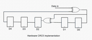
The problem is that in many cases shift register implementation is suboptimal. It only allows the calculation of one bit every clock. If a design has 32-bit wide datapath, meaning that every clock CRC module has to calculate CRC on 32-bit of data, this scheme will not work. Somehow this serial shift register implementation has to be converted into a parallel N-bit wide circuit, where N is the design datapath width, so that every clock N bits are processed.
I started researching the available literature on parallel CRC calculation methods and found only a handful of papers ([2], [3]) that deal with this issue. Most sources are academic and focus on the theoretical aspect of the problem. They are too impractical to implement in software or hardware for a quick code generation.
I came up with the following scheme that I’ve used to build an online Parallel CRC Generator tool. Here is a description of the steps in which I make use USB CRC5 mentioned above. 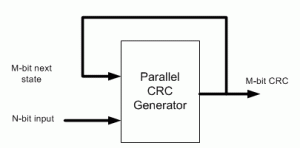
(1) Let’s denote N=data width, M=CRC width. For example, if we want to generate parallel USB CRC5 for 4-bit datapath, N=4, M=5.
(2) Implement serial CRC generator routine using given polynomial or hex notation. It’s easy to do in any programming language or script: C, Java, Perl, Verilog, etc.
(3) Parallel CRC implementation is a function of N-bit data input as well as M-bit current state CRC, as shown in the above figure. We’re going to build two matrices: Mout (next state CRC) as a function of Min(current state CRC) when N=0 and Mout as a function of Nin when M=0.
(4) Using the routine from (2) calculate CRC for the N values when Min=0. Each value is one-hot encoded, that is there is only one bit set. For N=4 the values are 0x1, 0x2, 0x4, 0x8. Mout = F(Nin,Min=0)
(5) Build NxM matrix, Each row contains the results from (3) in increasing order. For example, 1’st row contains the result of input=0x1, 2’nd row is input=0x2, etc. The output is M-bit wide, which the desired CRC width. Here is the matrix for USB CRC5 with N=4.
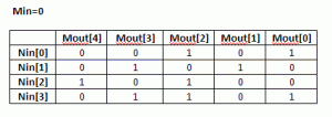
(6) Each column in this matrix, and that’s the interesting part, represents an output bit Mout[i] as a function of Nin.
(7) Using the routine from (3) calculate CRC for the M values when Nin=0. Each value is one-hot encoded, that is there is only one bit set. For M=5 the values are 0x1, 0x2, 0x4, 0x8, 0x10. Mout = F(Nin=0,Min)
(8) Build MxM matrix, Each row contains the results from (7) in increasing order. Here is the matrix for USB CRC5 with N=4
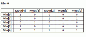 (9) Now, build an equation for each Mout[i] bit: all Nin[j] and Min[k] bits in column [i] participate in the equation. The participating inputs are XORed together.
Mout[0] = Min[1]^Min[4]^Nin[0]^Nin[3]
Mout[1] = Min[2]^Nin[1]
Mout[2] = Min[1]^Min[3]^Min[4]^Nin[0]^Nin[2]^Nin[3]
Mout[3] = Min[2]^Min[4]^Nin[1]^Nin[3]
Mout[4] = Min[0]^Min[3]^Nin[2]
That is our parallel CRC.
I presume since the invention of the CRC algorithm more than 40 years ago, somebody has already came up with this approach. I just coulnd’t find it and “reinvented the wheel”.
Keep me posted if the CRC Generation tool works for you, or you need more clarifications on the algorithm.
[September 29th, 2010] Users frequently ask why their implementation of serial CRC doesn’t match the generated parallel CRC with the same polynomial. There are few reasons for that:
– bit order into serial CRC isn’t the same as how the data is fed into the parallel CRC
– input data bits are inverted
– LFSR is not initialized the same way. A lot of protocols initialize it with F-s, and that’s what is done in the parallel CRC.
|
|
Download a full version of this article |
References
- CRC on Wikipedia
- G. Campobello, G Patane, M Russo, “Parallel CRC Realization”
- W Lu, S. Wong, “A Fast CRC Update Implementation”

Hello! Recently,I’m studying the CRC,your work is very helpful to me,your explanation of the algorithm is also very clear.But I have a question about the tool “crc-gen.exe”,I’ve been taught that when the shift register is initialized for all-ones,Before the algorithm to deal with,the first n-bit message data bits must be reverse,but not the case in crc-gen.exe,I want to know Why.I hope that you have time to e-mail me.Thanks!
Thanks for the interest in my parallel CRC generator.
I think there is no connection between initializing the LFSR with ‘1’s and reversing the data bits. Non-zero initialization is intended for detecting leading ‘0’ bit sequences in the data.
Reversing data bits is a protocol-specific way to calculate CRC. I think it’d be incorrect to reverse data bits in the first n-bit message and not in subsequent ones.
Can you please point me to the source that tells doing that.
Thanks for your answer. I can understand that all-ones initialization is intended for detecting leading ‘0′ bit sequences in the data,but how to understand the result which is different from the remainder of direct long division operation. so I think this is the reason it reverse the first n-bit data bits.
the source is come from the chinese version of CRC on Wikipedia.
Thanks!
Hi,
There is a much simpler way to do this. 🙂
e.g. in VHDL, write a function to calculate 1 bit of the CRC. Then, inside a clocked process, run a for loop and call this function multiple times. e.g. if you want to generate 8 bits of CRC per clock, the function gets called 8 bits. This synthesises and meets timing just fine.
You will find actual code by Mike Treseler on comp.arch.fpga to do this. It works well.
Cheers
Andrew
Hi Andy,
You’re right, it can be done that way. The synthesis tool will then “unroll” the for loop and generate XOR tree. However, I found that directly coded XOR tree produces more compact logic, at least in case of Xilinx XST. More details are in this document.
Thanks,
Evgeni
Hi,
It is easy to understand and nicely written. Just have a basic doubt while going through the Matrix generation for parallel CRC. Logic for NxM metrix is clear. But bit confused on MxM matrix. It is of width of required CRC. While geneting MxM matrix do we need to consider the data width?(How it would reflect here) .
I tried to gererate logic for Parallel CRC with two combinations
1. N=4 and M=5
2. N=8 and M=5 Same equation just for a sek of understanding.
Here in both the cases MxM matix would be different though we are using same equation/polynomial. Can you please help to understand how to take care of it.
Hi Manesh,
MxM matrix is a function of the next CRC state given the current state, while data bits are zero. Still, it does depend on the data width N. That’s because serial CRC is calculated N times after the initialization.
Thanks,
Evgeni
Hi,
I saw your paper.It is quite useful.
I am working on the BCH code.In that I wanted to apply my information bits as a byte wise.Do you have any idea regarding that.Please reply me if you know anything about how to implement Bch code.
Thanks in advance
Krupesh
Hi Krupesh,
I’d expect the approach I describe also applies to the BCH. However, I don’t know BCH deep enough to be certain.
Thanks,
Evgeni
Thank you very much for replying me.
I have one more question.Suppose I have 16 bytes of data on which I want to apply CRC.I am using 8 bit parallel CRC then how to implement this.And Should I calculate my CRC polynomial according to 16 bytes of data or 1 byte of data.
Regards,
Krupesh
Hi,
One more thing I want to ask.I saw your code.I simulated it in modelsim.I gave four bits inputs and I checked the outputs.After that I created a serial model for your code.And I gave inputs same as before but serially.Now I am getting the outputs which is different from previous one.I think both results should same.May be I did some mistake.So would you please check this.
Regards,
Krupesh
Hi Krupesh,
You specify 8-bit data width and it’d take 16 clocks to calculate such a CRC, 1-byte at a time.
Thanks,
Evgeni
@krupesh
Yes, serial and parallel CRC results should be the same.
Thanks,
Evgeni
@Evgeni
I’m studying the CRC, your website is very helpful to me.
I have a few question about the CRC, Could you please give me some help?
——————–
Here is my problem.
1. lfsr(3:0)=1+x^3+x^4,
2. bitstream=”1011001″,
3. CRC=”1010″
Theoretically, if the input is “10110011010”, and after all these bits is shifted into CRC module, the CRC output will be zero. But, when I initiate the lfsr_q register with “1111”, the output will be not-zero; when I initiate the register with “0000”, the output will be all-zeros.
I am still confused about that all-one initiation, Could you please give me some help about it?
Another question is about the parallel CRC, if the datawidth is 8, data_in(0) is msb or lsb?
Thanks a lot!
Hi,
(1) The reason CRC LFSR is usually initialized with ‘1’s is to prevent the situation when all-zero data, or a long stream of leading zeros will cause the LFSR value not to change (we do want it to change for every data bit).
(2) The bit order is implementation-specific. But it’s not important in general implementation as soon as CRC generator on the tx side and CRC checker on the rx side follow the same order.
Hope that helps,
Evgeni
hi,
i am working on programmable crc i.e. so that i can change crc_key every time
in short i want to provide input data ,crc_key as input and want computed crc at output
i wrote a code but its sort of recursive involving XOR operation with key on data and shifting
do you have any idea how can i increase parallelism it further
Hi,
For small enough CRCs you can use a look-up table approach to make it programmable. But this will not scale well for larger CRCs.
Evgeni
but in look up table based aproach we need to create look up table at run time when ever key changes that consumes some time ,comparing that with the total computation time this aproach will deliver the same performance
Hi,
I was doing a project regarding this.Since we are taking data of width 8 every time,So 2^8=256 combinations.As for Crc generation we have to append n zeroes to the data width and divide it by divisor polynomial of n+1 bits.So once we calculate manually the 256 remainders and store in a look up table and everytime for certain data combination,remainder particular to that can be the output crc.Can this technique work faster?
Hi,
Which part of the technique do you want to work faster?
The one with storing all remainders in lookup table.
Hi, I’m not very at ease with english so please excuse my mistakes. I want to make a CRC code in VHDL following the CCITT protocol it means the polynum must be x^16+x^12+x^5+1 and i’m lost trying to apply your algo to this polynum. My entry data width is 24 bits. Could you please tell me the logic that changes regarding the CRC16 USB2.2 protocol?? I would appreciate if you could send me the code at my adress maxlamenace04[at]hotmail[dot]com for me to try to understand the changes.
Hi Max,
Just select 24 in the data width, 16 in the poly width, and check the correct polynomial values: 1,5,12.
Thanks,
Evgeni
thanks, it works i thought only some protocol were available. Thank you very much really, it’s a very convenient tool you made.
hey, i have a question regarding CRC32 calculation when input data is a 1 byte long. I am using your code in my project but i can’t seem to get the right crc i guess.
1- Do i need to reverse the bit order of each input byte or not ?
2- Do i need to complement the final crc value before transmitting ?
thanks
Hi Hassan,
There are different variants of CRC32, and each one has its implementation specifics. It’s usually defined in the protocol you use (Ethernet, PCI, etc.) whether to reverse the bits or complement the final CRC.
Thanks,
Evgeni
Thanks Evgeni, i am generating ethernet’s crc and i have read it on many sites that you have to reverse the bit order,on the contrary there is an equal number of sites saying that you dont need to reverse the bit order. But anyway, thanks a lot, your site is of great help to me =)
Hi, I have a question about the figure of LFSR in CRC HW. In your article, “A Practical Parallel CRC generation Method”, the LFSR for CRC5 implementaion is designed in a different way from the way Wikipedia has explained. The URL is as follows,
http://en.wikipedia.org/wiki/Computation_of_CRC#Parallel_computation_without_table.
Accoring to this website, data bit affects the lsb of crc value only. However, the LFSR in your article doesn’t. I’m very confused.. Which one is right?
Thanks,
Jeongsup Lee
Hi Jeongsup,
I’m not sure they’re different: in both the data bit is fed into an XOR gate. Perhaps you’re referring to the Galois vs Fibonacci implementation difference.
Thanks,
Evgeni
Hi Evgeni
I’m having some problems implementing the CRC32 with datawidth= 64 bits in a Spartan6.
My problem are the constraints not met. I’m trying to put it working at 160MHz but it don’t reach that.
Is it possible to pipeline a CRC? That would resolv my problem but I don’t know how to implement it.
Hi Chico,
I worked with CRC32 and datawidth=256 bit that run at 133MHz on Virtex4. I’d expect your configuration to meet timing. But before you resort to pipelining, I’d recommend trying to floorplan it.
Thanks,
Evgeni
Hi,
I am trying to understand CRC generation using the shift register, could someone help to explain how it works, thanks.
regards
Essennell
Hi,
I think a good place to start with understanding a 1-bit CRC is on wiki: http://en.wikipedia.org/wiki/Cyclic_redundancy_check
Thanks,
Evgeni
Hi,
A quick question, I’ve just read your PDF “circuit-cellar-january-2010-crc.pdf”. And you’ve explained to me privously that you use Galois notation.
At the step where you generate the matrixes with your software LFSR implementation, which i guess is implemented with Galois notation. Is it possible to use a Fibonacci notation insted?
And will the reset of the proceedure still hold ?
Hi,
Galois and Fibonacci notations are used to describe linear feedback shift registers, which are used for CRC with 1-bit data.
Parallel CRC in my method is using XOR trees, which is a structure different from LFSR. It reduces to Galois-style LFSR for 1-bit data.
Thanks,
Evgeni
Ok,
Im not completly clear if that answer is a yes or no :D. However, i know that the XOR trees are not a LFSR. My question, dont know if i have been unclear, is that the matrixes you use to calculate thoes XOR tress are based on a calculation made over a software implementation of a Galois LFSR. My question is will the same method work if the Matrix is made by a software implemented Fibonacci LFSR insted ?
Hi,
The method should work with either Fibonacci or Galois LFSRs. I expect that both will produce the same result – matrix coefficients, or XOR tree – but will need to work out a formal proof for that claim.
Thanks,
Evgeni
i am giving a date packet but not able to see the correct crc
Hi Vikram,
There is a long list of things that can go wrong during CRC calculation. I’d need more information to help you.
Thanks,
Evgeni
Hi Evgeni,
thanks for your kind reply.
can you remove the code part which i have pasted above from the blog, as i am using it in my project.and i have got out of the problem.now i have writen a new code other than this.i have got the output.but it was very helpfull with the this site where i learnt a lot how the crc really works,before which i was seeing lot of papers.
Thanks a lot
vikram
@Evgeni
Hello Evgeni, I am working on an Ethernet CRC-32 hardware block.
The Verilog code that is generated by this website doesn’t seem to work out of the box.
I used two sources of test data:
1) http://www.lammertbies.nl/comm/info/crc-calculation.html (checking the CRC-32 result)
2) a DOCSIS (cable modem encryption spec) that uses CRC-32.
I generated the RTL, built a testbench, and this is what I found out:
Input data: 0x01020304
Expected CRC: 0xB63CFBCD (according to the crc-calculation.html)
In order to match this, I had to
1) REVERSE the endianness of each input byte, meaning instead of sending in 0x01020304, i had to send in {reverse(0x01), reverse(0x02), etc.}. wikipedia does state that in Ethernet, the bytes are little endian.
2) Invert every bit of output CRC value from the generated RTL (this is specified in some Ethernet specs as the “final inversion”)
3) Then REVERSE the endianness of the entire value, i.e. [31:0] maps to [0:31].
In addition, I tested this value specified as a DOCSIS example:
data: 0x010203040506_F1F2F3F4F5F6_000102030405060708090A0B (24 bytes)
Expected CRC (from the crc-calculation.html): 0x06654188
Expected CRC (from the DOCSIS example): 0x884165006
You can see that in DOCSIS, the byte ordering within a 32-bit word is reversed. Aside from that issue, doing steps 1) through 3) above with the generated RTL matched the results.
So, I have two questions:
1) Is all of this bit endianness reversal expected/required?
and a big question:
2) How do I handle a residual amount of data? For example, what if I send in (4 + *2*) or (4 + *3*) bytes into this 32-bit RTL? I’m not sure how this code can deal with that situation, unless there is a padding method that I am unaware of. I cannot get this stuff to match no matter what I do.
-Dardy
Hi Dardy,
I can recommend this Xilinx appnote that discusses Ethernet CRC.
To your questions:
(1) Unfortunately, there is no “universal” way to implement CRC. For various reasons almost every protocol I’ve encountered with has its own requirement, such as endianness, LFSR init value, byte order, etc. It’s sometimes frustrating and time consuming to get it right. Basically, it’s not the matter of what’s expected; you just have to follow the protocol spec.
(2) There are few ways to deal with the residual data. Padding will not work. You can either have 8-bit CRC that calculates CRC on 1..3 bytes, but it might take up to 3 clocks. Or you can have 8, 16, and 24-bit CRC modules. That will take one clock, but more logic. More elegant algorithm to deal with the residual data is frequently called “byte enable” CRC, and described in the paper by A. Simionescu: “CRC Tool: Computing CRC in Parallel for Ethernet,” Nobug Consulting. It’s not supported by the CRC generator on this site.
Thanks,
Evgeni
Hallo!
I tried your parallel crc generator and I simulated it using Xilinx ISE. I made simple tests to evaluate it, but I haven’t got success.
Steps I made:
1. Generate VHDL source file with parameters:
Data with: 26 bits
CRC with: 4 bits: 1+x^1+X^4
2. Copy and paste to Xilinx ISE
3. I did simple test: When input data = b”0..01″ crc should be crc polynomial without leading one: 0011. It is (after 26 clocks)
4. When input data contains only crc polynomial (00..10011), crc should be zero.
It isn’t. CRC according to Xilinx simulator = 0xd. (26th clock)
5. I try reverse bit order: input data = “000..11001”) => CRC= 0xb.
Where do I do mistake?
Sorry for my english.
Hi Tibor,
I’d suggest trying to simplify the system. Can you try generating the same CRC polynomial, but with data width=1 (serial). If the results still don’t match the expected, then there might be something to do with the incorrect polynomial initialization. CRC generator initializes it with all-Fs, but it can be easily changed.
Thanks,
Evgeni
@Evgeni
Evgeni, THANK YOU for your prompt response.
So I have one basic question then: what does this outputlogic.com CRC code generator assume? From all my trial and error, it looks like is assumes what I said: 1) little endian bytes coming in and 2) a little endian result. Something like that. I HATE endianness issues. But I’d just like to know what this code assumes (as far as endianness issues) so I know what I need to do with it.
I will look into the residual (8, 16, 24, etc.) issue. Thanks a ton. This is a GREAT forum for CRC hardware people. 🙂
-Dardy
@Evgeni
Evgeni, THANK YOU for your prompt response.
So I have one basic question then: what does this outputlogic.com CRC code generator assume? From all my trial and error, it looks like is assumes what I said: 1) little endian bytes coming in and 2) a little endian result. Something like that. I HATE endianness issues. But I’d just like to know what this code assumes (as far as endianness issues) so I know what I need to do with it.
I will look into the residual (8, 16, 24, etc.) issue. Thanks a ton. This is a GREAT forum for CRC hardware people. 🙂
OH. I have a quick question about the residual stuff. I don’t need to pre-initialize to all F’s, right? This is an initialization thing for certain CRC standards, so I assume that for residual data, this doesn’t need to be done.
-Dardy
Hi Dardy,
That’s right, you don’t need to pre-initialize with F’s.
Thanks,
Evgeni
Hi Evgeni
I m facing some problems. In Listing-3 in the paper, does line no. 4 mean:
M_out = CRC_Serial (Nin[i], M_out); ????
That is, we send only a single bit of input data to CRC_Serial function in each iteration (4 in this case).
Secondly in Table-1 (H1 matrix), what these rows represent? I did hand calculation for N_in = 0001, initial M_in = 00000 and doing 4 call to CRC5_SERIAL function (listing-2). In each iteration, I sending it single data bit (starting from LSB = 1 for N_in = 0001) and using M_Out values from previous iteration. I was able to build Table-1. But now I am confused about N_in values of 0x2, 0x4 and 0x8. Are these used to build any matrix?
I’ll be thankful if you could indicate what I am doing wrong.
Thanks
BluSky
Hi,
M_out = CRC_Serial (Nin, M_out); The same function is called N times, which is the number of parallel data bits.
H1 is a transition matrix. Each row represents a one-hot encoded N_in: 0x1…0x8
Thanks,
Evgeni
Hallo!
I tried your parallel crc generator and I simulated it using Xilinx ISE. I made simple tests to evaluate it, but I haven’t got success. and hoe to checking for transmit side and receiving side .i have implementation of crc 8,32,16 simple polanamials serial data_input ,but how to check it both sides ,and if any algorithm fo crc with using for input 8_ bit and 16, 32, 4 bits data
Steps I made:
Data with: 26,4,,32,16bits if any ..how to implementation
2. Copy and paste to Xilinx ISE
3. I did simple test: When input data 1,= b”0..01″ crc should be crc polynomial without leading one: 0011. It is (after 26 clocks)
4.how to check for output packets ?
Sorry for my english.